
On this page:
Components of a solar photovoltaic (PV) system
Rooftop solar PV systems have become a common sight on Australian residential roofs over the past 15 years. While the benefits of rooftop solar (including reduced carbon emissions and electricity bills) are evident, they can make the process of electrically isolating a home more complex. As many solar PV wires are run through ceiling spaces, it is integral they are isolated before work commences.
Isolating a solar PV system at a residential home is more complex than simply isolating all switches at the main switchboard, including the PV ARRAY MAIN SWITCH. Isolation is also required at the solar inverter and potentially on DC isolators, which may be located elsewhere.
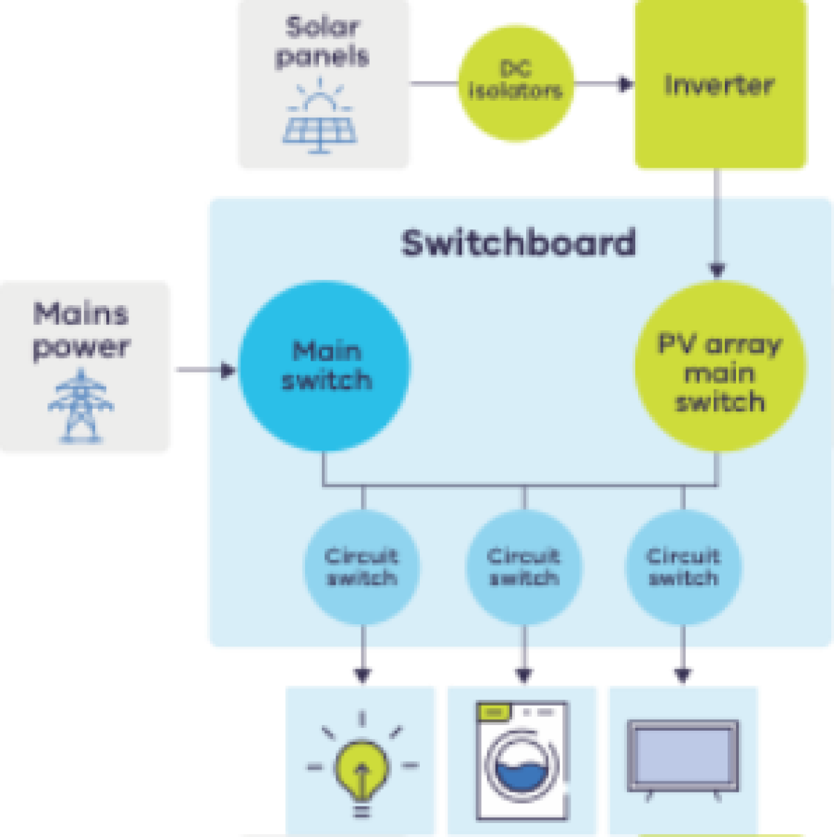
Figure 1 shows components of an electrical system that need to be isolated before performing rooftop insulation work.
- Items in blue are components in all homes that require isolation.
- Items in green are components unique to homes with rooftop solar that may require isolation. This includes the inverter (converts DC power from panels to AC for use in homes) and DC isolators.
Figure 1: Components of a residential solar photovoltaic system
How to safely isolate a solar photovoltaic system
Solar PV and battery systems require extra steps to safely isolate electricity before performing rooftop insulation work. These steps are described next.
Part 1: Solar PV and battery signage
Australian Standards (specifically AS 4777.1:2024) require electrical switchboards to have signage installed if a solar PV or battery system is connected to the installation. Common examples are shown in Figures 2 to 4.
Figure 2:
- Left: Sign near switchboard to indicate presence of PV system
- Right: Sign near switchboard to indicate presence of Battery system
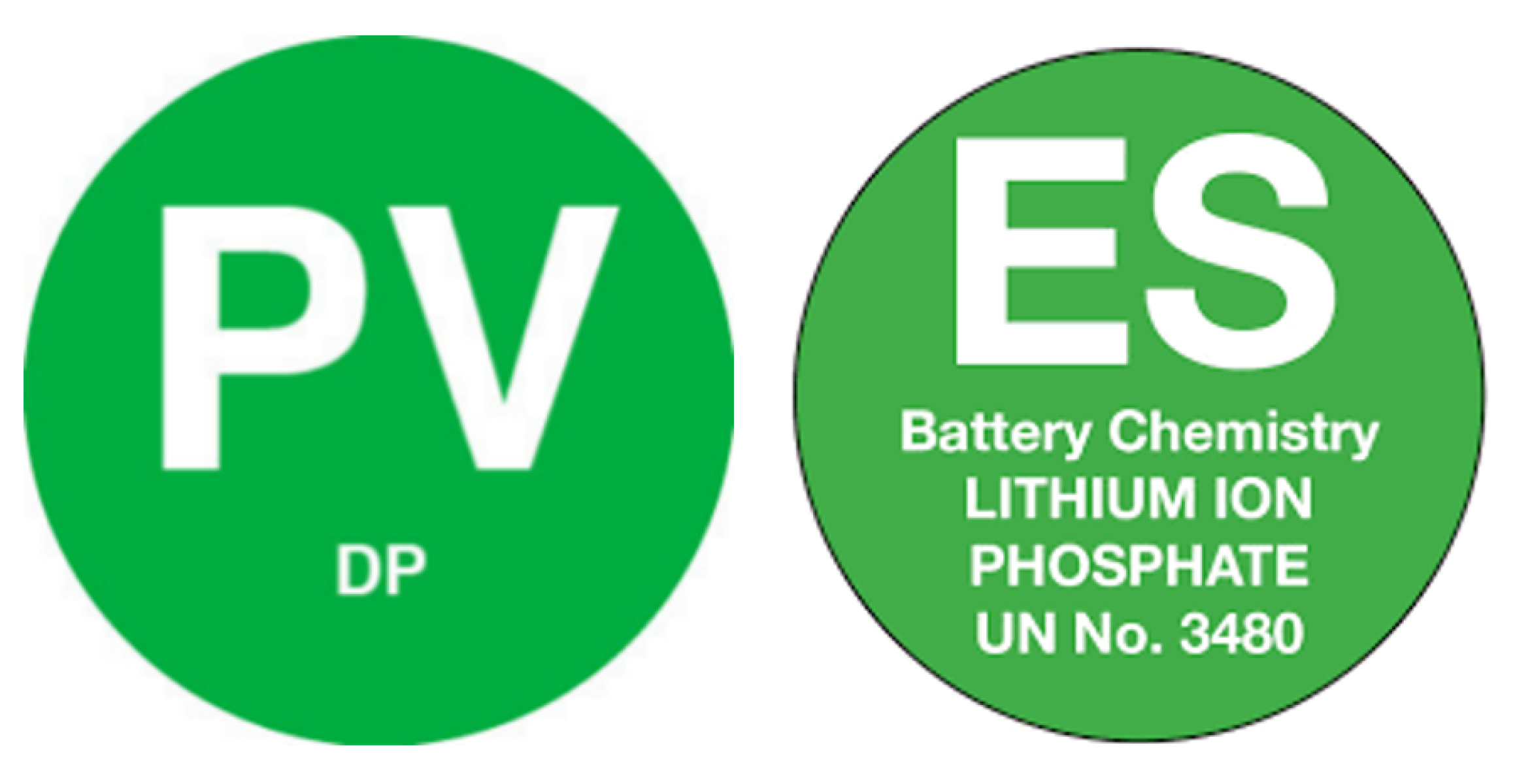
Figure 3: Warning sign indicating multiple electricity supplies
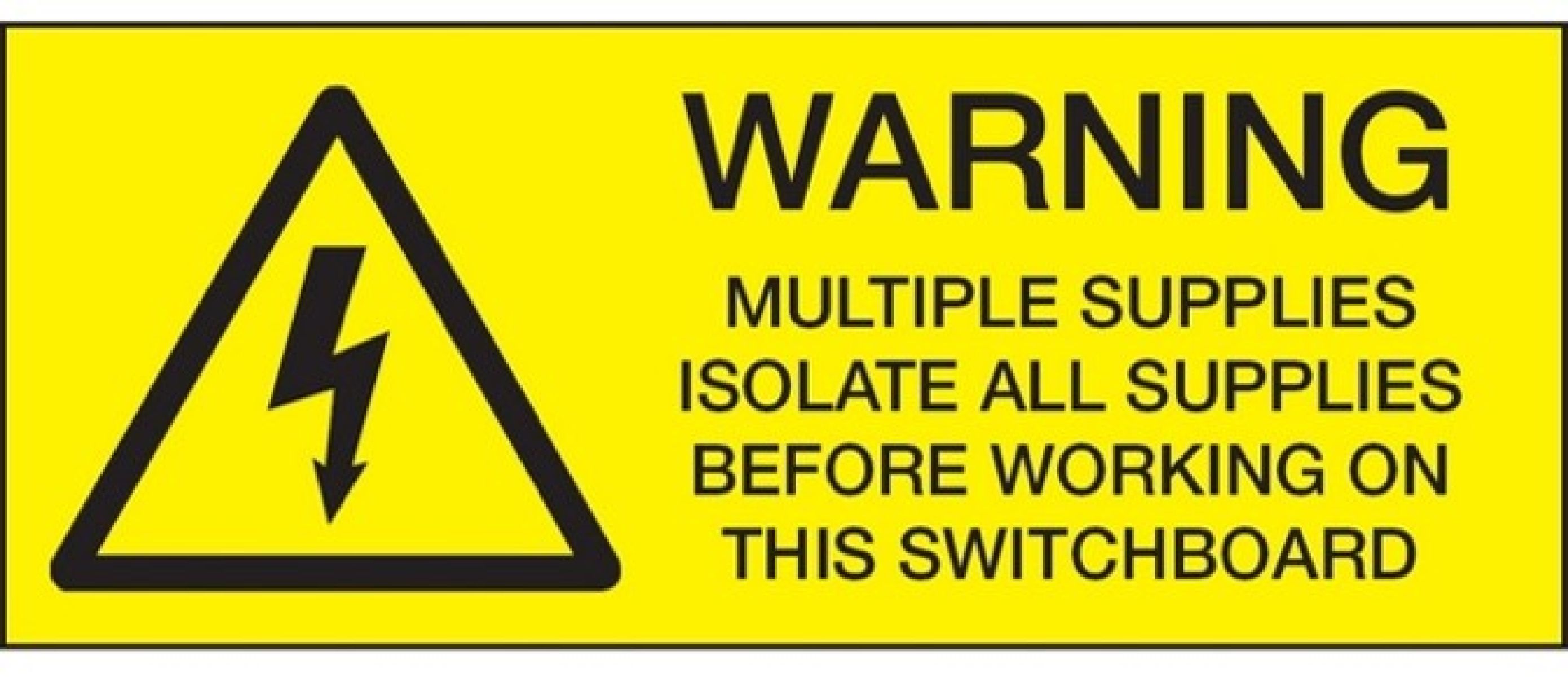
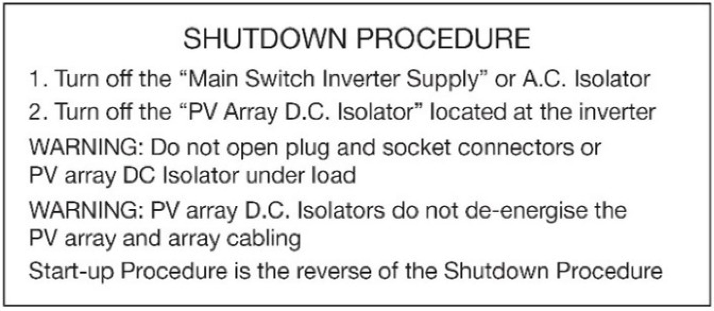
Figure 4: Shutdown procedure sign showing how to safely isolate the solar PV system
These signs clearly indicate that rooftop solar or a battery is present, and that simply isolating at the switchboard will not be sufficient to ensure safety.
Part 2: Isolating the main switchboard
In most scenarios, the first step is to safely isolate the main switchboard by following these steps:
- Identify all sources of electricity.
- Isolate the main switchboard.
- Lock out the isolation point.
- Tag out the isolation point.
Refer to Guidance Sheet 3.1 – Safe elements of electrical isolation for a comprehensive guide on how to disconnect
However, it is important to note that if an electrical system is isolated only by switching and locking off the circuits at the main switchboard, some components may still be live. This includes:
- Inverter and DC isolators: without properly switching off the inverter (and DC Isolators if required), solar photovoltaic panels may continue to produce electricity, resulting in cables being live.
- Mains power to the switchboard will still be active.
Isolating the main switchboard does not make a residential solar PV system fully safe. Even after isolation at the switchboard, parts of the system remain energised. Live components (shown in Green) can still include connections to main supply, as well as the DC cabling between the solar panels and the inverter, and the wiring from the inverter to the switchboard.
Figure 5: Live components of a residential electrical system after isolation is achieved at the switchboard
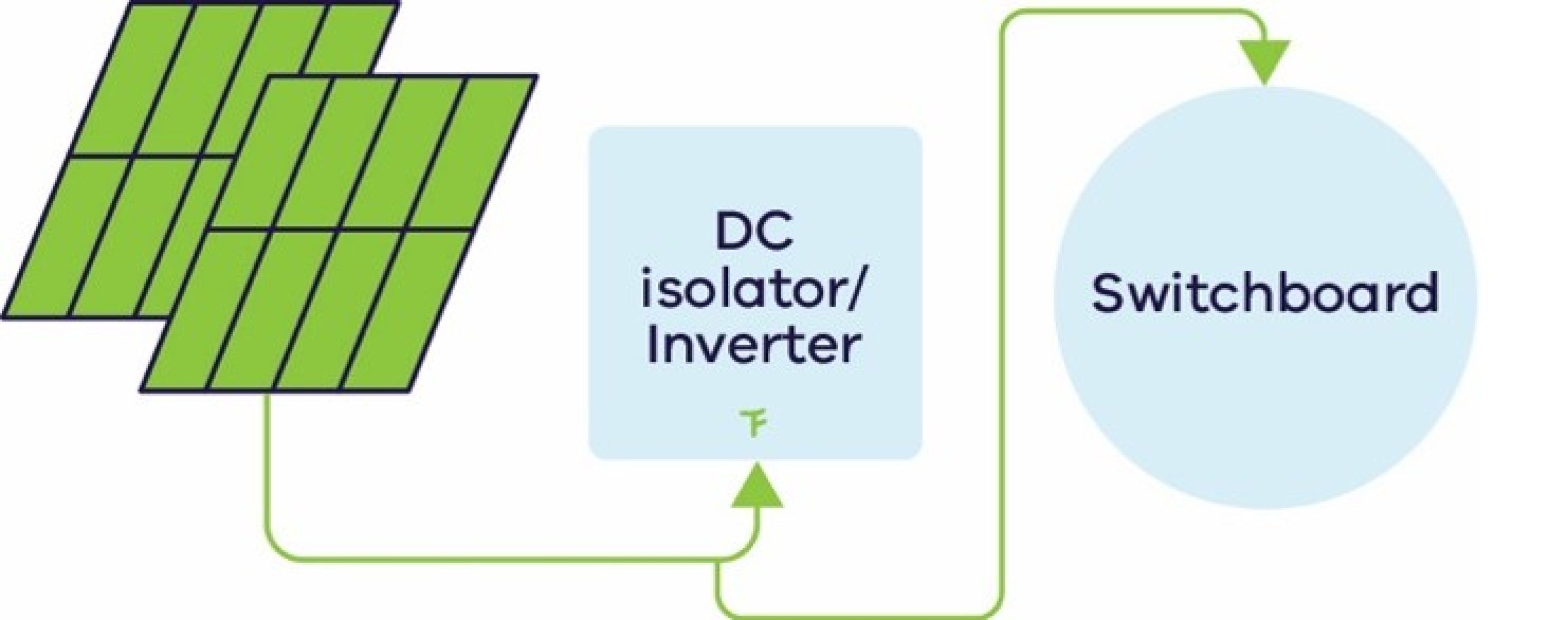
Live components are shown in green and include any connections to mains power, as well as the connections between solar panels and the DC isolator/inverter, and from the inverter to the switchboard.
Part 3: Follow the shutdown procedure
Follow the shutdown procedure for the solar system (and battery system, if present) to safely ensure these systems are not operational before starting work.
Typically, for solar photovoltaic systems (also shown in Figure 6), the shutdown procedure involves:
- switching off the “Main Switch Inverter Supply” (at the switchboard)
- turning off the “PV Array – D.C. Isolator”. This is normally located close to the inverter.
Figure 6: Shutdown procedure instructions
Note: This does not isolate the cabling from the PV Array to the inverter, which will remain active. These cables should be labelled SOLAR PV DC CIRCUIT or PHOTOVOLTAIC POWER SOURCE.
Battery systems also have a specified shutdown procedure which should be followed.
Part 4: Test isolation and take ongoing precautions
Confirm that the isolation was effective by testing the electrical installation for voltage. This can be done in the following ways:
- testing internal/external lighting circuits
- testing for absence of voltage using an appropriate test instrument, for example multimetre
- checking that socket outlets are de-energised, for example using a plug-in tester or metre
- confirming that household appliances, such as microwaves or televisions, cannot be switched on.
- erifying that all relevant circuits, including solar PV supply, are de-energised.
It is prudent to treat any cable as live, even after performing isolation of electrical sources. This is particularly important when working on homes with solar installed as some wires can remain live despite shutting down the inverter.
Download a copy of this guidance sheet
Continue through the guidance series
Page last updated: 01/10/26